Carrier Rfl 0601el Manual
• Control Module Communication.4 Carrier Comfort Network Interface.4 OPERATING DATA. • CONTENTS (cont) • LEAD/LAG DETERMINATION • CAPACITY SEQUENCE DETERMINATION • CAPACITY CONTROL OVERRIDES Head Pressure Control.27 •.
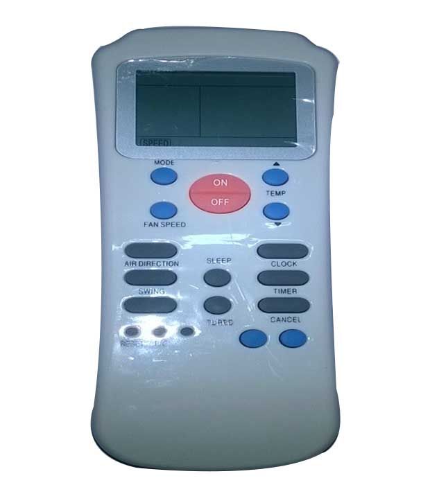
Graphik font family download. Carrier Rfl-0601ehl User Manual For Carrier RFL-0601EHL RFL-0601NEHL RLF-0301E 36KCARMS AC Air Conditioner Remote Control ----- Where to see the latest. Get free help, tips & support from top experts on manual carrier 36kcarms related I lost the user´s manual of my wireless remote control model RFL-0601EHL. CARRIER AIR CONDITIONER Remote Control RFL-0601E, RFL-0601EH, RFL-0601EL NEW - $18.50. Brand New Carrier Replacement Remote Control. This after-market remote replaces the following Carrier remote models: RFL-0601E, RFL-0601EH, RFL-0601EL. To check which model your remote is, check the back of the remote.
• Information is transmitted between modules via a 3-wire com- UNIT 30GTN,R munication bus or LEN (Local Equipment Network). The — — CCN (Carrier Comfort Network) bus is also supported. Con- — nections to both LEN and CCN buses are made at TB3. • YELLOW LED — The MBB has one yellow LED. The Carrier Comfort Network (CCN) LED will blink during times of network communication. Carrier Comfort Network (CCN) Interface — The 30GTN,R chiller units can be connected to the CCN if desired.
• CR-A1 CR-A1 CR-A1 LEGEND FOR FIG. 1-4 — Compressor Contactor — Circuit Breaker — Carrier Comfort Network — Compressor Ground Fault — Cooler Heater Thermostat — Circuit — Cooler Heater Relay — Compressor Protection and Control System — Chilled Water Flow Switch —.
• DATA COMMUNICATION PORT Fig. 2 — 24 V Control Schematic, Unit Sizes 040-070. • DATA COMMUNICATION PORT Fig. 3 — 24 V Control Schematic, Unit Sizes 080-110, 230B-315B Fig.
3 — 24 V Control Schematic, Unit Sizes 080-110, 230B-315B. • DATA COMMUNICATION PORT Fig. 4 — 24 V Control Schematic, Unit Sizes 130-210, 230A-315A, 330A/B-420A/B. • LEN (LOCAL EQUIPMENT NETWORK) CEPL130346-01 STATUS Fig.
6 — Enable/Off/Remote Contact Switch, Emergency On/Off Switch, YELLOW LED - CCN (CARRIER COMFORT NETWORK) Fig. 5 — Main Base Board RESET BUTTON (SIZES 130-210 AND ASSOCIATED MODULES ONLY) and Reset Button Locations. • OPERATING DATA Sensors — The electronic control uses 4 to 10 thermistors to sense temperatures for controlling chiller operation. These sensors are outlined below.
7-10 for thermistor locations. Thermistors T1-T9 are 5 kΩ at 77 F (25 C).
• 040-070 080-110 AND ASSOCIATED MODULAR UNITS* 130-210 AND ASSOCIATED MODULAR UNITS* *When thermistor is viewed from perspective where the compressor is on the left and the cooler is on the right. 8 — Thermistor T3 and T4 Locations.
• LEGEND EXV — Electronic Expansion Valve Fig. 9 — Compressor Thermistor Locations (T7 and T8) Fig. 10 — Typical Thermistor Location (30GTN,R and 30GUN,R 210, 315A, 390A, 420A/B Shown) • The space temperature sensor includes a terminal block (SEN) and a RJ11 female con- nector. The RJ11 connector is used to tap into the Carrier Com- fort Network (CCN) at the sensor. To connect the space temperature sensor (Fig.
• Thermostatic Expansion Valves (TXV) — 30GTN,R and 30GUN,R 040-110 units are available from the factory with conventional TXVs with liquid line solenoids. The liquid line solenoid valves are not intended to be a mechanical shut-off.
When service is required, use the liquid line service valve to pump down the system. • Electronic Expansion Valve Fig. 15) — Standard units are equipped with a bottom seal EXV.
This device eliminates the use of the liquid line solenoid pumpdown at unit shutdown. An O-ring has been added to bot- tom of orifice assembly to complete a seal in the valve on shut- down. • CEBD4-01C STATUS RED LED - STATUS The capacity control algorithm runs every 30 seconds. The algorithm attempts to maintain the leaving chilled water tem- perature at the control point.